Scale model wind tunnel testing explained
How Wind tunnels Work – Blockage factor, wall effects, scaled model, similarity number, moving floor
The key to a successful test programme is to replicate real-world conditions. In wind tunnel testing that means testing objects at full scale and at high velocity wind speeds. However, when testing aircraft, lorries or cars, suitable full scale tunnels either don’t exist or have limited availability.
To get round this issue, companies develop scale models which can then be tested in smaller wind tunnels. By using a few aerodynamic tricks to manipulate the Reynolds number and wind tunnel velocity it is possible to achieve representative flow patterns when testing at scale.
Wind tunnel testing problems
Blockage ratio
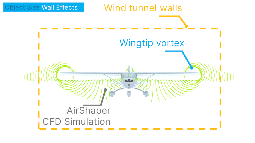
In reality, when air flows around an object, such as an aircraft, it is free to expand in three dimensions. For a ground vehicle it is free in two dimensions, due to the proximity of the ground. A wind tunnel on the other hand, is limited in all dimensions by the walls, roof and floor of the working section. If these are too close, the resulting contraction will force the flow to speed up around the model, leading to inaccurate results.
This is called the blockage effect and gets worse as the blockage factor (the ratio between the model cross section and the tunnel cross section) increases. Once determined, the blockage factor can be used to calculate the local flow velocity and correct the necessary pressure and forces. In general, it is recommended to keep this blockage factor below 5-10% to obtain reliable results.

Boundary layers
Another problem with testing in wind tunnels is the effect of boundary layers. Air flowing over a solid surface will create a boundary layer which is the region where air speed drops from free stream to zero.
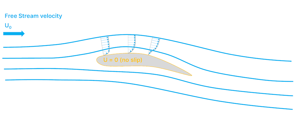
In the real world, boundary layers are not an issue in many applications, apart from on roads. However, in a wind tunnel, boundary layers are present on the walls, floor and ceiling. Therefore, when conducting wind tunnel tests, it's important for the characteristics of the boundary layers to match with reality.
Furthermore, the walls of the wind tunnel can also interfere with the flow and pressure patterns surrounding an object if they are too close. To help understand the extent of these issues, CFD can be a useful tool to examine the predicted flow field around an object.
Overall, the blockage effect together with the interference and boundary layers of the wind tunnel walls limits the size of objects that can be placed within a working section. However, testing scale models comes with a whole new set of challenges and correlation issues which have to be addressed to maintain accurate results.
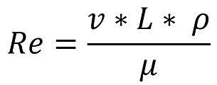
Reynolds number
In the late 1800s, Osborne Reynolds was working on what would later be named the Reynolds number. This number is used to compare different flow regimes, in particular characterising whether the flow is laminar or turbulent. For any test set-up, Reynold’s number is given by using fluid density (r), velocity (v), viscosity (µ) and a reference dimension of the object under test (L).
One of the most important factors to consider when using scale models is the Reynolds number. To achieve the same flow patterns when testing a scale model, the Reynolds number needs to match the Reynolds number used in full scale testing. Essentially, to keep the Reynolds number the same when scaling down an object size by a factor X, you need to scale up the wind speed by a factor X.
For example, if L is 50% of full scale, then to match the full-size Reynolds number something has to be done with r, u or µ. Doubling the speed or density or halving the viscosity would work. In reality, this is not so simple, however.
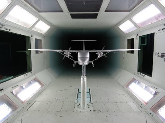
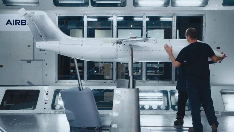
Wind tunnel models
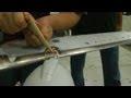
The items under test are always referred to as models, but this doesn’t do justice to the level of detail and effort that goes into their engineering. Many models will have hundreds of surface pressure tappings to allow measurement of static pressure. Alongside the load data, this gives a detailed view of the mechanisms creating the forces.
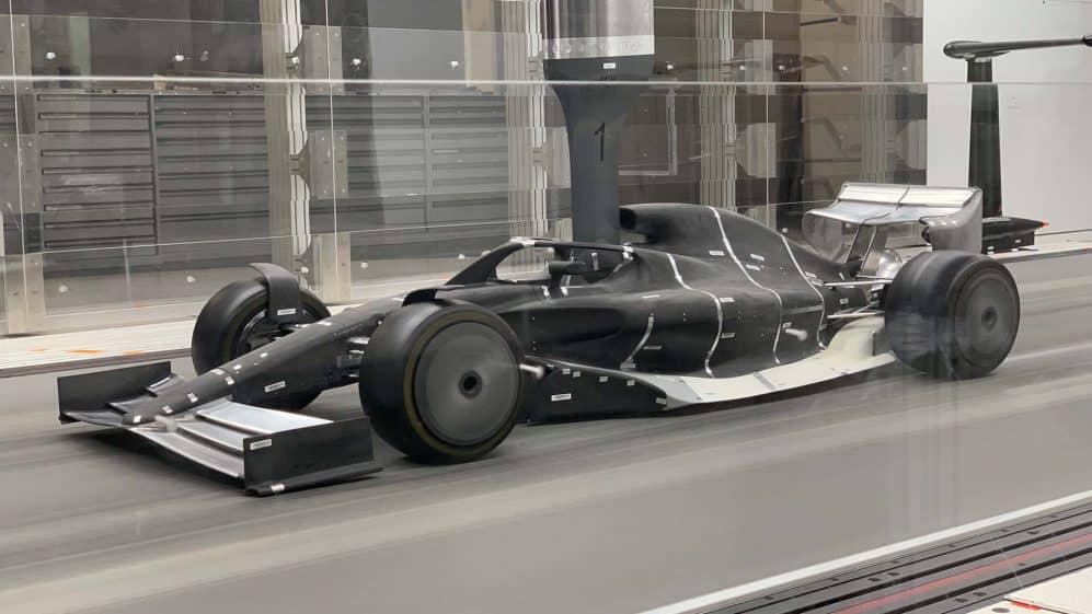
A 60%-scale Formula One car model for example, will usually have fully-working suspension, steering and even exhaust flow! Moving parts can be controlled as part of the wind tunnel test sequence.
The skeleton of the model will usually be modular and metallic. The external, air-washed surfaces may be machined or 3D-printed using stereolithography. As 3D printing techniques have improved, pressure tapping channels can now be integrated within the model and are carefully built to ensure accuracy. Ironically, this can lead to correlation issues. Often, the model is built so well that the surface imperfections of the real vehicle lead to poorer aerodynamic performance when compared to the model.
Controlling wind tunnel models
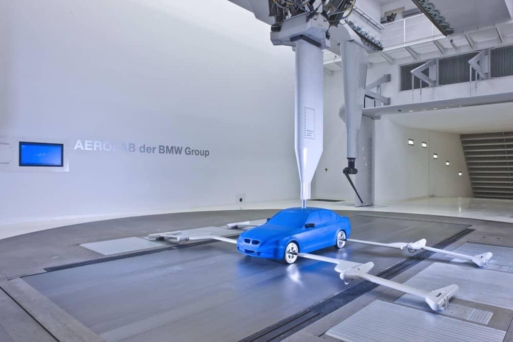
There are many different ways to suspend or support wind tunnel models. Early automotive tunnels tended to support the wheels with stings from the side of the tunnel, whilst the main model was suspended from above. This was to prevent the model support load balance from bridging or distorting.
If the wheels are connected to the model and run on the belt, the balance will not measure all of the loads. However, without load on the tyres, the sidewall shape will be unrepresentative. The latest automotive wind tunnels have load cells under the rolling road with a high-pressure air bearing system to allow load to be measured “through” the belt.
In general, ground vehicles are typically supported from above, while scale aircraft models can be supported from the rear or below. The important factor is that the sting should be designed in such a way to minimise interference with the model.
The support mechanism has two main jobs. Firstly, it transfers aerodynamic loads to the main balance. This is a very accurate load transducer capable of measuring forces and moments in all three axes. Secondly, it allows the model to be moved within the air flow to represent different angles of attack, yaw or ride heights.
For a ground vehicle, the balance may be in the model or at the top of the sting. Motion is usually via a hexapod, which is able to move the model in heave, roll, pitch and yaw. The latter is required either to match the yaw of the road or can be used to yaw the model itself relative to the road.
Continuous motion
Most wind tunnel tests are carried out in a series of movement steps. For an aircraft or a wing, this might be a range of angles of attack. After each movement, the air flow is allowed to settle before load measurements are taken. Generally, this will be a time averaged number over a few seconds to maintain accuracy and evaluate small changes.
In Formula One, rule changes over the last decade have continually cut down the amount of wind tunnel time teams can use. This has led to the development of continuous motion systems. The model is constantly moved through a range of conditions and averaging samples are taken over small sections as it moves.
Consequently, there is no dead time of movement waiting for the air to settle, saving time and making the test more efficient. This method of testing does requires a lot of effort to ensure high quality results, though. It is particularly difficult to manage the wind-on and wind-off zeroing procedures required to ensure offsets do not affect data.

